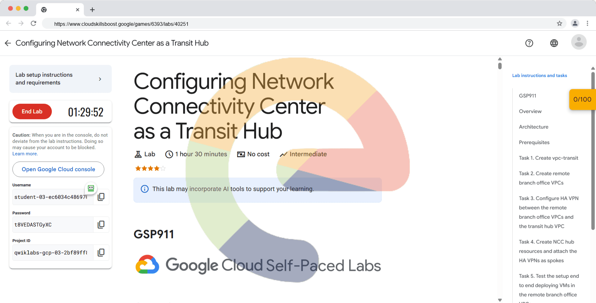
Configuring Network Connectivity Center as a Transit Hub - GSP911
A passionate full-stack developer from @ePlus.DEV
Overview
Network Connectivity Center (NCC) enables connecting different enterprise networks together that are outside of Google Cloud by leveraging Google's network—providing enterprises instant access to planet-scale reach and high reliability. Traffic between non-Google networks is referred to as data transfer traffic, which can occur using existing standard cloud network connectivity resources such as Cloud VPN, Dedicated or Partner Interconnect.
In this lab, you will go through the process of setting up NCC as a transit hub to route traffic between two non-Google networks using Google's backbone network.
Architecture
NCC consists of hub and spoke resources.
Hub
A hub is a global Google Cloud resource that supports multiple attached spokes. It provides a simple way to connect spokes together to enable data transfer across them. A hub can provide data transfer between different on-premises locations and a Virtual Private Cloud (VPC) network through its attached spokes.
Spoke
A spoke is a Google Cloud network resource connected to a hub. It is part of the hub, and can't be created without creating the hub first. A spoke routes traffic to remote network address blocks and enables the connection of multiple remote networks.
Spokes can be of one of the following types:
HA VPN tunnels
VLAN attachments
Router appliance instances that you or select partners deploy within Google Cloud
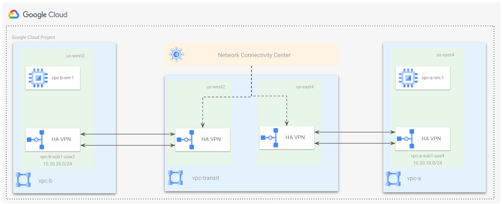
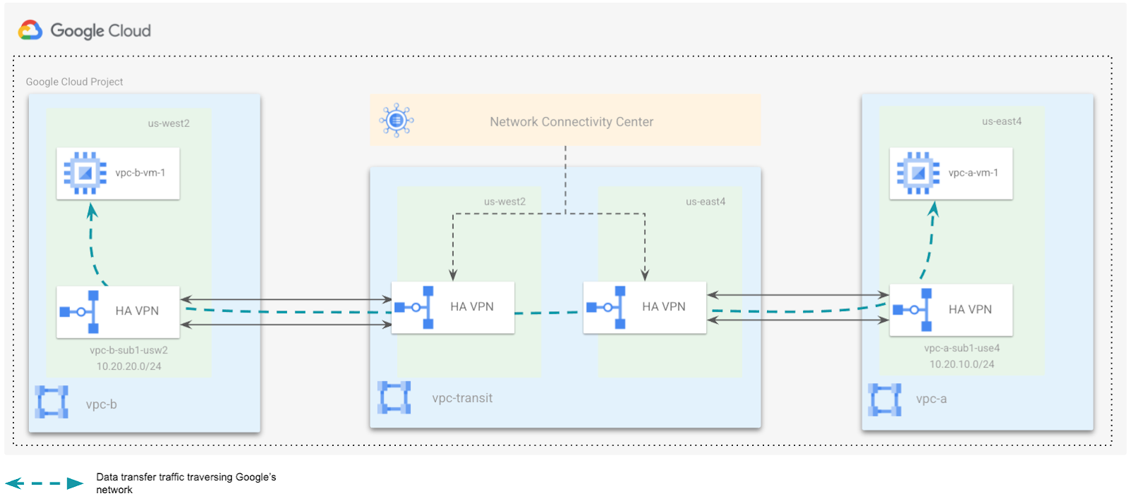
The following network topology is similar to a typical customer deployment having branch offices located in two geographically separate locations. For this lab, you are simulating two VPCs vpc-a, and vpc-b in us-east4, and us-west1 as the branch offices respectively.
The branch offices are connected to a VPC, vpc-transit, which is a central hub terminating a pair of HA VPNs. These VPNs are configured in a region closest to the branch offices. In the real world, these VPNs could be replaced using Interconnects.
You will configure the NCC hub in the vpc-transit network, and the two remote branch offices will be connected using the HA VPN tunnels as spokes.
In this lab, you will achieve the following objectives:
Create a hub VPC called vpc-transit.
Create two remote branch office VPCs namely vpc-a and vpc-b.
Create HA VPN from vpa-a to vpc-transit, and vpc-b to vpc-transit.
Create a NCC hub resource and attach the HA VPNs as spokes.
Test the setup end to end deploying VMs in the remote branch office VPCs.
Prerequisites
Basic knowledge of Google VPC Networking, and Compute Engine.
It is helpful to have completed the Networking 101 and VPC Networking: Cloud HA-VPN labs.
Task 1. Create vpc-transit
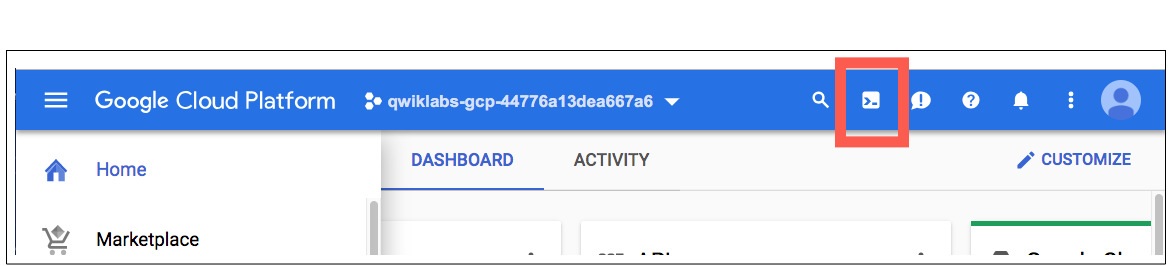
- In the Google Cloud console, in the top-right toolbar, click the Activate Cloud Shell button and run the following command to delete the default network.
gcloud compute networks delete default
In the Google Cloud console, from the Navigation Menu (
), go to VPC network.
Click CREATE VPC NETWORK.
Enter a Name for the network: vpc-transit.
You do not need to create a subnet for the vpc-transit so click Delete next to New Subnet.
Choose the Dynamic routing mode for the VPC network as Global.

Note: Learn more about dynamic routing from the dynamic routing mode documentation.
- Click Create.
Click Check my progress to verify the objective.
Create vpc-transit network
Task 2. Create remote branch office VPCs
In the Google Cloud console, from the Navigation menu, go to the VPC network.
Click CREATE VPC NETWORK.
Enter a Name for the network as vpc-a.
Choose Custom for the Subnet creation mode.
In the New subnet section, specify the following configuration parameters for a subnet:
Name for the subnet: vpc-a-sub1-use4.
Region:
us-east4.IP address range 10.20.10.0/24. This is the primary IP range for the subnet.
Click Done.
Choose the Dynamic routing mode for the VPC network as Regional.
Click Create.
To add the second remote branch office VPC, click CREATE VPC NETWORK.
Enter a Name for the network as vpc-b.
Choose Custom for the Subnet creation mode.
In the New subnet section, specify the following configuration parameters for a subnet:
Provide a Name for the subnet as vpc-b-sub1-usw2.
Select Region as
us-west1.Enter an IP address range 10.20.20.0/24.
Click Done.
Choose the Dynamic routing mode for the VPC network as Regional.
Click Create.
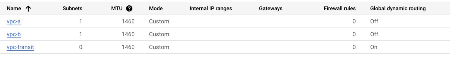
Now you should be able to view all 3 VPCs in the VPC networks console like this:
Click Check my progress to verify the objective.
Create remote branch office VPCs namely vpc-a and vpc-b
Task 3. Configure HA VPN between the remote branch office VPCs and the transit hub VPC
Note: In this lab you are simulating the remote branch offices as Google Cloud VPCs, therefore using the steps listed to Create HA VPN between Google Cloud Networks.
For any practical implementation, you may replace the steps listed below with the steps for Creating an HA VPN gateway to a peer VPN gateway if you are using HA VPNs to connect to your branch offices.
In this section you will configure an HA VPN between the remote branch office VPCs (vpc-a and vpc-b) and the transit hub VPC (vpc-transit). HA VPN uses BGP for dynamically exchanging routes between Google Cloud and the peer network. Before configuring the HA VPNs, you need to create Cloud Routers associated with each VPC network.
Note: Learn more about Cloud Routers in the Cloud Router overview documentation.
Step 1: Create cloud routers
To create a new Cloud Router for each VPC, specify the following:
On the Google Cloud console title bar, type Network Connectivity in the Search field, then click Network Connectivity from the Search results.
Click Pin next to Network Connectivity.
Select Cloud Router, and click Create router.
Enter name as cr-vpc-transit-use4-1.
Select the network as vpc-transit.
Select the region as
us-east4.Enter the Cloud Router ASN as 65000.
Select Advertise all subnets visible to the Cloud Router (Default).
Click Create.
Use the steps mentioned above to create additional cloud routers using the following details:
| Name | Network | Region | Cloud Router ASN |
| cr-vpc-transit-usw2-1 | vpc-transit | us-west1 | 65000 |
| cr-vpc-a-use4-1 | vpc-a | us-east4 | 65001 |
| cr-vpc-b-usw2-1 | vpc-b | us-west1 | 65002 |
Step 2: Create HA VPN gateways
Create an HA VPN gateway in the vpc-transit network for us-east4 region, using the following steps:
From the Navigation menu, go to Network Connectivity and select VPN.
Click Create VPN connection.
Select High-availability (HA) VPN.
Click Continue.
Specify a VPN gateway name as vpc-transit-gw1-use4.
For Network, select vpc-transit.
Select a Region as
us-east4.Click Create and continue.
Note: Before adding VPN tunnels, you need to create additional VPN gateways.
From Add VPN tunnels page, click Cancel.
Select Cloud VPN Gateways, and click Create VPN Gateway.
Use the step mentioned to create the additional VPN gateways using the following details:
| VPN gateway name | VPC Network | Region |
| vpc-transit-gw1-usw2 | vpc-transit | us-west1 |
| vpc-a-gw1-use4 | vpc-a | us-east4 |
| vpc-b-gw1-usw2 | vpc-b | us-west1 |
Click Check my progress to verify the objective.
Create cloud routers and HA VPN gateways
Step 3: Create a pair of VPN tunnels between vpc-transit to vpc-a
Add VPN tunnels from vpc-transit to vpc-a
Create a pair of VPN tunnels using the following steps:
From the VPN page, click on Cloud VPN Gateways and select vpc-transit-gw1-use4.
Click to Add VPN tunnel.
For the Peer VPN Gateway, select Google Cloud VPN Gateways.
Select the Project Id associated with the lab.
Select the remote VPN gateway, vpc-a-gw1-use4.
For high availability, select Create a pair of VPN tunnels.
Select the Cloud Router cr-vpc-transit-use4-1.
Click on the VPN tunnel to enter the tunnel details:
The Cloud VPN and the associated peer VPN gateway interface information should be pre-populated
Name: transit-to-vpc-a-tu1
IKE version: IKEv2
IKE pre-shared key: gcprocks
Click Done.
Repeat steps for the second tunnel:
Name: transit-to-vpc-a-tu2
IKE version: IKEv2
IKE pre-shared key: gcprocks
Click Done.
Click Create & Continue.
Add BGP sessions for each VPN tunnel configured from vpc-transit to vpc-a
The next step is to configure BGP session for the VPN tunnel transit-to-vpc-a-tu1
Click Configure BGP Session for transit-to-vpc-a-tu1:
BGP session name: transit-to-vpc-a-bgp1
Peer ASN: 65001
Allocate BGP IPv4 address: Manually
Cloud Router BGP IPv4 address: 169.254.1.1
BGP peer IPv4 address: 169.254.1.2
Click Save and continue.
- Repeat steps to configure BGP session for the VPN tunnel transit-to-vpc-a-tu2.
- Click Configure BGP Session for transit-to-vpc-a-tu2:
BGP session name: transit-to-vpc-a-bgp2
Peer ASN: 65001
Allocate BGP IPv4 address: Manually
Cloud Router BGP IPv4 address: 169.254.1.5
BGP peer IPv4 address: 169.254.1.6
Click Save and continue.
Click on Save BGP configuration.
Click OK.
Add VPN tunnels from vpc-a to vpc-transit
Now create a pair of VPN tunnels from the vpc-a to vpc-transit to complete the bidirectional tunnel configuration using the following steps:
From the VPN page, select Cloud VPN Gateways vpc-a-gw1-use4:
Click to Add VPN tunnel.
For the Peer VPN Gateway, select Google Cloud VPN Gateways.
Select the Project Id associated with the lab.
Select the remote VPN gateway, vpc-transit-gw1-use4
For high availability, select Create a pair of VPN tunnels.
Select the Cloud Router, cr-vpc-a-use4-1
Click on the VPN tunnel to enter the tunnel details:
The Cloud VPN and peer VPN gateway interface information should be pre-populated.
Name: vpc-a-to-transit-tu1
IKE version: IKEv2
IKE pre-shared key: gcprocks
Click Done.
Repeat steps for the second tunnel:
Name: vpc-a-to-transit-tu2
IKE version: IKEv2
IKE pre-shared key: gcprocks
Click Done.
Click Create & Continue.
Add BGP sessions for each VPN tunnel configured from vpc-a to vpc-transit
The next step is to configure BGP session for the VPN tunnel: transit-to-vpc-a-tu1
Click Configure BGP Session for vpc-a-to-transit-tu1
BGP session name: vpc-a-to-transit-bgp1
Peer ASN: 65000
Allocate BGP IPv4 address: Manually
Cloud Router BGP IPv4 address: 169.254.1.2
BGP peer IPv4 address: 169.254.1.1
Click Save and continue.
Repeat steps to configure BGP session for the VPN tunnel: transit-to-vpc-a-tu2
Click Configure BGP Session for vpc-a-to-transit-tu2
BGP session name: vpc-a-to-transit-bgp2
Peer ASN: 65000
Allocate BGP IPv4 address: Manually
Cloud Router BGP IPv4 address: 169.254.1.6
BGP peer IPv4 address: 169.254.1.5
Click Save and continue.
Click on Save BGP configuration.
Click OK.
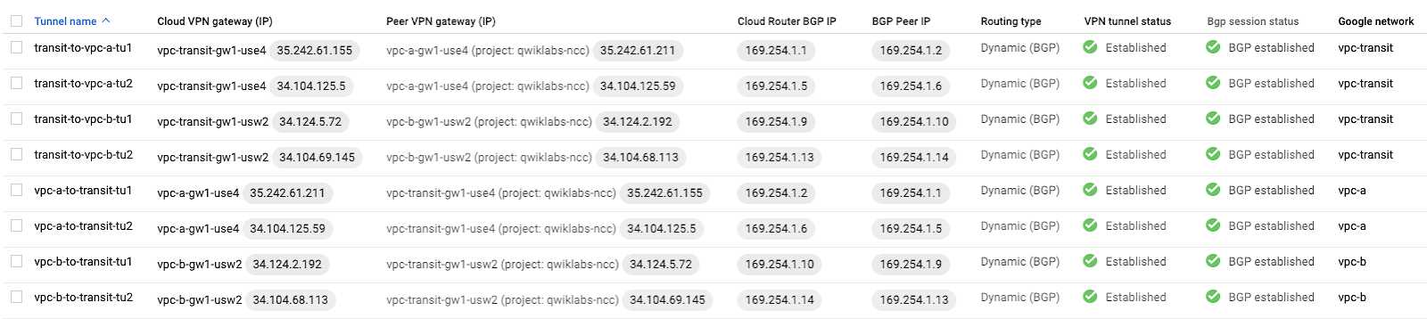
Once this step is complete the VPN tunnel status should reflect Established and BGP status should reflect BGP established.
Step 4: Create a pair of VPN tunnels between vpc-transit to vpc-b
- Repeat steps listed above (step 3) to create the bidirectional HA VPN tunnels between the vpc-transit and vpc-b networks using the details below.
Add VPN tunnels from vpc-transit to vpc-b
| Peer VPN gateway name | vpc-b-gw1-usw2 |
| Cloud Router | cr-vpc-transit-usw2-1 |
| VPN tunnel one | transit-to-vpc-b-tu1 |
| Pre-shared key | gcprocks |
| VPN tunnel two | transit-to-vpc-b-tu2 |
| Pre-shared key | gcprocks |
Add BGP sessions for each VPN tunnel configured from vpc-transit to vpc-b
BGP session for tunnel transit-to-vpc-b-tu1 :
| BGP session | transit-to-vpc-b-bgp1 |
| Peer ASN | 65002 |
| Cloud Router BGP IPv4 address | 169.254.1.9 |
| BGP peer IPv4 address | 169.254.1.10 |
BGP session for tunnel transit-to-vpc-b-tu2 :
| BGP session | transit-to-vpc-b-bgp2 |
| Peer ASN | 65002 |
| Cloud Router BGP IPv4 address | 169.254.1.13 |
| BGP peer IPv4 address | 169.254.1.14 |
Add VPN tunnels from vpc-b to vpc-transit
| Peer VPN gateway name | vpc-transit-gw1-usw2 |
| Cloud Router | cr-vpc-b-usw2-1 |
| VPN tunnel one | vpc-b-to-transit-tu1 |
| Pre-shared key | gcprocks |
| VPN tunnel second | vpc-b-to-transit-tu2 |
| Pre-shared key | gcprocks |
Add BGP sessions for each VPN tunnel configured from vpc-b to vpc-transit
BGP session for tunnel vpc-b-to-transit-tu1 :
| BGP session | vpc-b-to-transit-bgp1 |
| Peer ASN | 65000 |
| Cloud Router BGP IPv4 address | 169.254.1.10 |
| BGP peer IPv4 address | 169.254.1.9 |
BGP session for tunnel vpc-b-to-transit-tu2 :
| BGP session | vpc-b-to-transit-bgp2 |
| Peer ASN | 65000 |
| Cloud Router BGP IPv4 address | 169.254.1.14 |
| BGP peer IPv4 address | 169.254.1.13 |
Step 5: Verify the all the VPN connections status from the VPN page
- Scroll down the page to confirm that all connections are good.
Click Check my progress to verify the objective.
Create a pair of VPN tunnels between vpc-transit to vpc-a and vpc-b
Task 4. Create NCC hub resources and attach the HA VPNs as spokes
In this section you will create a VPC and create 2 subnets inside that VPC. This will all be done using gcloud CLI commands inside Google Cloud Shell.
Before you can perform any tasks for Network Connectivity Center, you must enable the Network Connectivity API.
From the Navigation Menu, search for API & Services.
Click on Library, and search for Network Connectivity API.
Select the Network Connectivity API.
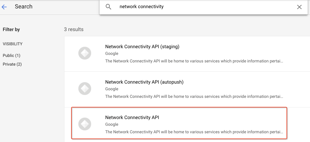
Click Enable.
In this lab
gcloudcommands are used to configure the Network Connectivity Center. In order to authorize Cloud Shell to run the gcloud commands, open the Google Cloud Shell by clicking Activate Cloud Shell().Run the following command to list the active account name:
gcloud auth list
- Click Authorize.
Step 1: Create NCC hub
- You can click on the "clipboard" icon in the upper right corner of the text box to copy the contents:
gcloud alpha network-connectivity hubs create transit-hub \
   --description=Transit_hub
Step 2: Create the spoke for branch office 1
- You can click on the "clipboard" icon in the upper right corner of the text box to copy the contents:
gcloud alpha network-connectivity spokes create bo1 \
    --hub=transit-hub \
    --description=branch_office1 \
    --vpn-tunnel=transit-to-vpc-a-tu1,transit-to-vpc-a-tu2 \
    --region=us-east4
Step 3: Create the spoke for branch office 2
- You can click on the "clipboard" icon in the upper right corner of the text box to copy the contents.
gcloud alpha network-connectivity spokes create bo2 \
    --hub=transit-hub \
    --description=branch_office2 \
    --vpn-tunnel=transit-to-vpc-b-tu1,transit-to-vpc-b-tu2 \
    --region=us-west1
Click Check my progress to verify the objective.
Create NCC hub resources and attach the HA VPNs as spokes
Task 5. Test the setup end to end deploying VMs in the remote branch office VPCs
After configuring the hub and its spokes, you should be able to pass traffic from the virtual machine (VM) instance in branch office1 to the VM instance in branch office2. To do this, create a vpc-a-vm-1 in vpc-a and vpc-b-vm-1 in vpc-b respectively.
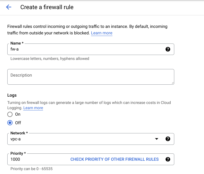
First, create firewall rules: fw-a for vpc-a-vm-1 in vpc-a-sub1-use4 subnet and fw-b for vpc-b-vm-1 in vpc-b-sub1-usw2 subnet respectively to allow ingress SSH and ICMP traffic.
Step 1: Create Firewall rule for vpc-a
In the Cloud Platform Console, click Navigation menu () at the top left of the screen.
Then navigate to VPC network > Firewall.
Click on CREATE FIREWALL RULE and specify the details as shown.
- Similarly, create firewall rule fw-b for vpc-b.
Step 2: Create VM in vpc-a
- In the Cloud console, on the Navigation menu (☰), click Compute Engine > VM Instances, then click Create instance.
Note: This may take a minute to initialize for the first time.
There are many parameters you can configure when creating a new instance. Use the following for this lab:
In the Machine configuration
Enter the values for the following fields:
| Field | Value | | --- | --- | | Name |
vpc-a-vm-1| | Region |us-east4| | Zone |us-east4-c| | Series |E2| | Machine |e2-medium|Click OS and storage
Click Change to begin configuring your boot disk and select the values for:
| Field | Value | | --- | --- | | Operating system |
Debian| | Version |Debian GNU/Linux 11 (bullseye) x86/64| | Boot disk type |balanced persistent disk| | Size (GB) |10 GB|Click Networking
Network interfaces : click on
defaultto edit.Network:
vpc-aSubnetwork:
vpc-a-sub1-use4
Once all sections are configured, scroll down and click Create to launch your virtual machine instance.
Note: The instance creation process is asynchronous. You can check on the status of the task using the top right-hand side Activities icon. Wait for it to finish - it shouldn't take more than a minute.
Note: If you receive an error when creating a VM, click into Details. Most likely you need to try again with a different zone.
Once finished, you should see the new virtual machine in the VM Instances page.
Similarly, create another VM in vpc-b using the following parameters:
In the Machine configuration
Enter the values for the following fields:
| Field | Value | | --- | --- | | Name |
vpc-b-vm-1| | Region |us-west1| | Zone |us-west1-c| | Series |E2| | Machine |e2-medium|Click OS and storage
Click Change to begin configuring your boot disk and select the values for:
| Field | Value | | --- | --- | | Operating system |
Debian| | Version |Debian GNU/Linux 11 (bullseye) x86/64| | Boot disk type |balanced persistent disk| | Size (GB) |10 GB|Click Networking
Network interfaces : click on
defaultto edit.Network:
vpc-bSubnetwork:
vpc-b-sub1-usw2
Once all sections are configured, scroll down and click Create to launch your virtual machine instance.
Once finished, you should see the two virtual machines in the VM Instances page.
- Copy the internal IP of vpc-b-vm-1.

Click Check my progress to verify the objective.
Create VMs in the remote branch office VPCs
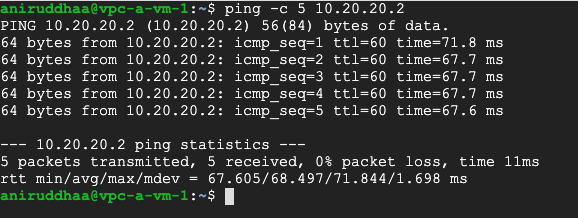
Step 3: Run the ping command and verify connectivity to bo2 via NCC transit
To verify the end to end connectivity, run a ping test between vpc-a-vm-1 and vpc-b-vm-1 using the following steps:
- SSH into vpc-a-vm-1 by clicking on SSH on the right hand side of vpc-a-vm-1. This launches a SSH client directly from your browser.
Note: You can also SSH into the virtual machine. Learn more about SSH from the Connect to an instance using ssh documentation.
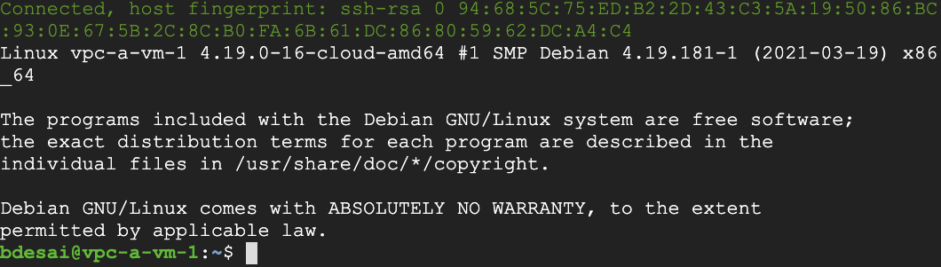
Run a ping test from vpc-a-vm-1 to the internal IP of vpc-b-vm-1.
You can click on the "clipboard" icon in the upper right corner of the text box to copy the contents.
ping -c 5 <INTERNAL_IP_OF_VPC-B-VM-1>
Solution of Lab
curl -LO raw.githubusercontent.com/Techcps/Google-Cloud-Skills-Boost/master/Configuring%20Network%20Connectivity%20Center%20as%20a%20Transit%20Hub/techcps911.sh
sudo chmod +x techcps911.sh
./techcps911.sh