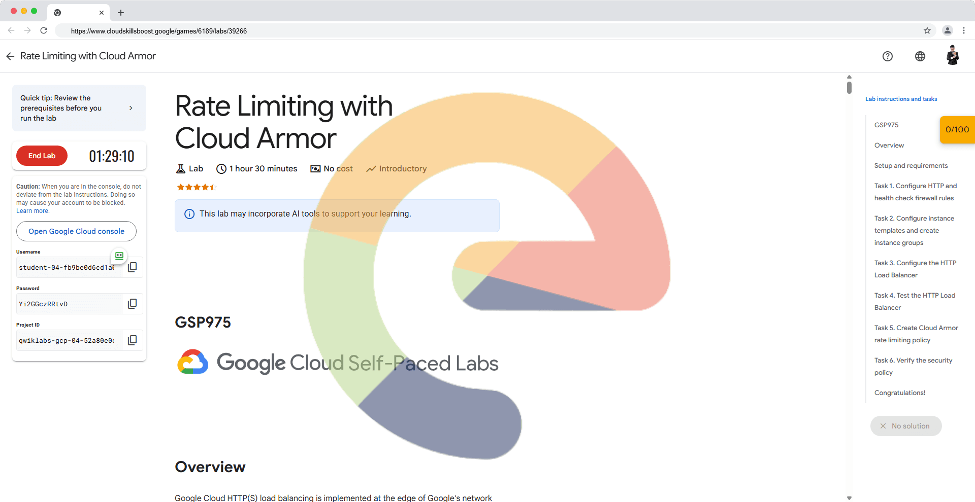
Rate Limiting with Cloud Armor - GSP975
A passionate full-stack developer from @ePlus.DEV
Overview
Google Cloud HTTP(S) load balancing is implemented at the edge of Google's network in Google's points of presence (POP) around the world. User traffic directed to an HTTP(S) load balancer enters the POP closest to the user and is then load balanced over Google's global network to the closest backend that has sufficient capacity available.
Cloud Armor IP allowlist/denylist enable you to restrict or allow access to your HTTP(S) load balancer at the edge of the Google Cloud, as close as possible to the user and to malicious traffic. This prevents malicious users or traffic from consuming resources or entering your virtual private cloud (VPC) networks.
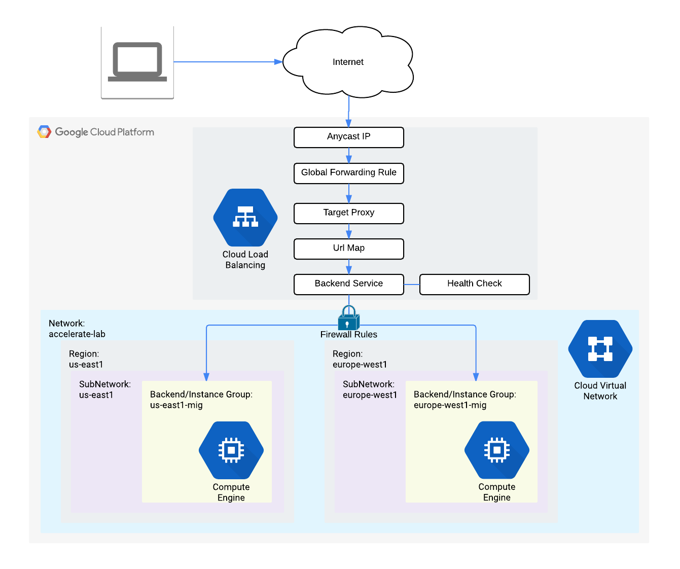
In this lab, you configure an HTTP Load Balancer with global backends, as shown in the diagram below. Then, you'll stress test the Load Balancer and add a Cloud Armor rate limiting policy to restrict based on IP.
What you'll learn
In this lab, you learn how to perform the following tasks:
Create HTTP and health check firewall rules
Configure two instance templates
Create two managed instance groups
Configure an HTTP Load Balancer with IPv4 and IPv6
Stress test an HTTP Load Balancer
Add a Cloud Armor rate limiting policy to restrict based on IP
Verify that traffic is getting blocked when running a stress test from a VM
Setup and requirements
Before you click the Start Lab button
Read these instructions. Labs are timed and you cannot pause them. The timer, which starts when you click Start Lab, shows how long Google Cloud resources are made available to you.
This hands-on lab lets you do the lab activities in a real cloud environment, not in a simulation or demo environment. It does so by giving you new, temporary credentials you use to sign in and access Google Cloud for the duration of the lab.
To complete this lab, you need:
- Access to a standard internet browser (Chrome browser recommended).
Note: Use an Incognito (recommended) or private browser window to run this lab. This prevents conflicts between your personal account and the student account, which may cause extra charges incurred to your personal account.
- Time to complete the lab—remember, once you start, you cannot pause a lab.
Note: Use only the student account for this lab. If you use a different Google Cloud account, you may incur charges to that account.
How to start your lab and sign in to the Google Cloud console
Click the Start Lab button. If you need to pay for the lab, a dialog opens for you to select your payment method. On the left is the Lab Details pane with the following:
The Open Google Cloud console button
Time remaining
The temporary credentials that you must use for this lab
Other information, if needed, to step through this lab
Click Open Google Cloud console (or right-click and select Open Link in Incognito Window if you are running the Chrome browser).
The lab spins up resources, and then opens another tab that shows the Sign in page.
Tip: Arrange the tabs in separate windows, side-by-side.
Note: If you see the Choose an account dialog, click Use Another Account.
If necessary, copy the Username below and paste it into the Sign in dialog.
student-04-fb9be0d6cd1a@qwiklabs.netYou can also find the Username in the Lab Details pane.
Click Next.
Copy the Password below and paste it into the Welcome dialog.
Yi2GGczRRtvDYou can also find the Password in the Lab Details pane.
Click Next.
Important: You must use the credentials the lab provides you. Do not use your Google Cloud account credentials.
Note: Using your own Google Cloud account for this lab may incur extra charges.
Click through the subsequent pages:
Accept the terms and conditions.
Do not add recovery options or two-factor authentication (because this is a temporary account).
Do not sign up for free trials.
After a few moments, the Google Cloud console opens in this tab.
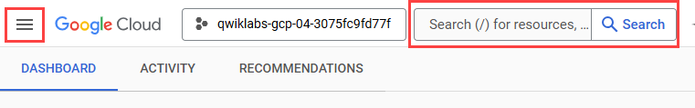
Note: To access Google Cloud products and services, click the Navigation menu or type the service or product name in the Search field.
Activate Cloud Shell
Cloud Shell is a virtual machine that is loaded with development tools. It offers a persistent 5GB home directory and runs on the Google Cloud. Cloud Shell provides command-line access to your Google Cloud resources.
Click Activate Cloud Shell at the top of the Google Cloud console.
Click through the following windows:
Continue through the Cloud Shell information window.
Authorize Cloud Shell to use your credentials to make Google Cloud API calls.
When you are connected, you are already authenticated, and the project is set to your Project_ID, qwiklabs-gcp-04-52a80e0e387e. The output contains a line that declares the Project_ID for this session:
Your Cloud Platform project in this session is set to qwiklabs-gcp-04-52a80e0e387e
gcloud is the command-line tool for Google Cloud. It comes pre-installed on Cloud Shell and supports tab-completion.
- (Optional) You can list the active account name with this command:
gcloud auth list
- Click Authorize.
Output:
ACTIVE: *
ACCOUNT: student-04-fb9be0d6cd1a@qwiklabs.net

To set the active account, run:
    $ gcloud config set account `ACCOUNT`
- (Optional) You can list the project ID with this command:
gcloud config list project
Output:
[core]
project = qwiklabs-gcp-04-52a80e0e387e
Note: For full documentation of gcloud, in Google Cloud, refer to the gcloud CLI overview guide.
Task 1. Configure HTTP and health check firewall rules
Configure firewall rules to allow HTTP traffic to the backends and TCP traffic from the Google Cloud health checker.
Create the HTTP firewall rule
Create a firewall rule to allow HTTP traffic to the backends.
In the Cloud Console, navigate to Navigation menu () > VPC network > Firewall.
Notice the existing ICMP, internal, RDP, and SSH firewall rules.
Each Google Cloud project starts with the default network and these firewall rules.
Click Create Firewall Rule.
Set the following values, leave all other values at their defaults:
Property
Value (type value or select option as specified)
Name
default-allow-http
Network
default
Targets
Specified target tags
Target tags
http-server
Source filter
IPv4 Ranges
Source IP ranges
0.0.0.0/0
Protocols and ports
Specified protocols and ports, and then check tcp, type: 80
Note: Make sure to include the /0 in the Source IP ranges to specify all networks.
Click Create.
Create the health check firewall rules
Health checks determine which instances of a load balancer can receive new connections. For HTTP load balancing, the health check probes to your load balanced instances come from addresses in the ranges 130.211.0.0/22 and 35.191.0.0/16. Your firewall rules must allow these connections.
Still in the Firewall rules page, click Create Firewall Rule.
Set the following values, leave all other values at their defaults:
Property
Value (type value or select option as specified)
Name
default-allow-health-check
Network
default
Targets
Specified target tags
Target tags
http-server
Source filter
IPv4 Ranges
Source IP ranges
130.211.0.0/22,35.191.0.0/16Protocols and ports
Specified protocols and ports, and then check tcp
Note: Make sure to enter the two Source IP ranges one-by-one and press SPACE in between them.
Click Create.
Click Check my progress to verify the objective.
Configure HTTP and health check firewall rules
Check my progress
Task 2. Configure instance templates and create instance groups
A managed instance group uses an instance template to create a group of identical instances. Use these to create the backends of the HTTP Load Balancer.
Configure the instance templates
An instance template is an API resource that you use to create VM instances and managed instance groups. Instance templates define the machine type, boot disk image, subnet, labels, and other instance properties. Create one instance template for us-central1 and one for europe-west4.
In the Cloud Console, navigate to Navigation menu (
) > Compute Engine > Instance templates, and then click Create instance template.
For Name, type
us-central1-template.For Location, Select Global.
For Series, select E2.
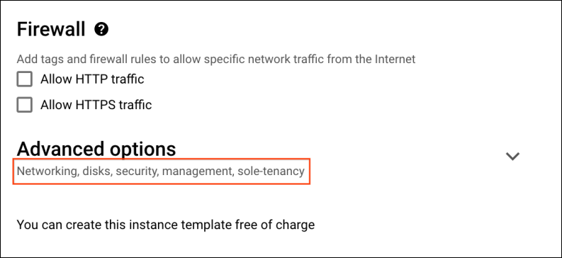
Click Networking, disks, security, management, sole-tenancy.

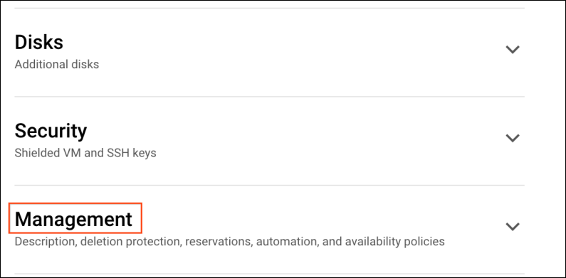
- Click the Management tab.
Under Metadata, click +ADD ITEM specify the following:
Key
Value
startup-script-url
gs://cloud-training/gcpnet/httplb/startup.sh
Note: The startup-script-url specifies a script that executes when instances are started. This script installs Apache and changes the welcome page to include the client IP and the name, region, and zone of the VM instance. Feel free to explore this script.
Click Networking, for Network tags, type
http-server.For Network interfaces expand default network and set the following values.
Property
Value (type value or select option as specified)
Network
default
Subnet
default (
us-central1)
Note: The network tag http-server ensures that the HTTP and Health Check firewall rules apply to these instances.
Click Create.
Wait for the instance template to be created.
Now create another instance template for subnet-b by copying us-central1-template:
Click on
us-central1-template and then click on the CREATE SIMILAR option from the top.For Name, type
europe-west4-template.For Location, Select Global.
Click Networking, disks, security, management, sole-tenancy.
Click Networking, expand
defaultnetwork.For Subnet, select default (
europe-west4).Click Create.
Create the managed instance groups
Create a managed instance group in us-central1 and one in europe-west4.
In the Navigation menu () click Compute Engine > Instance groups in the left menu.
Click Create instance group.
Set the following values, leave all other values at their defaults:
Property
Value (type value or select option as specified)
Name
us-central1-migLocation
Multiple zones
Region
us-central1Instance template
us-central1-templateAutoscaling > Autoscaling signals (click the dropdown icon to edit) > Signal type
CPU utilization
Target CPU utilization
80, click Done.
Initialization period
45
Minimum number of instances
1
Maximum number of instances
5
Note: Managed instance groups offer autoscaling capabilities that allow you to automatically add or remove instances from a managed instance group based on increases or decreases in load. Autoscaling helps your applications gracefully handle increases in traffic and reduces cost when the need for resources is lower. You just define the autoscaling policy and the autoscaler performs automatic scaling based on the measured load.
Click Create.
Now repeat the same procedure for create a second instance group for europe-west4-mig in europe-west4:
Click Create Instance group.
Set the following values, leave all other values at their defaults:
Property
Value (type value or select option as specified)
Name
europe-west4-migLocation
Multiple zones
Region
europe-west4Instance template
europe-west4-templateAutoscaling > Autoscaling signals (click the dropdown icon to edit) > Signal type
CPU utilization
Target CPU utilization
80, click Done.
Initialization period
45
Minimum number of instances
1
Maximum number of instances
5
Click Create.
Click Check my progress to verify the objective.
Configure instance templates and instance group
Check my progress
Verify the backends
Verify that VM instances are being created in both regions and access their HTTP sites.
Still in Compute Engine, click VM instances in the left menu.
Notice the instances that start with
us-central1-migandeurope-west4-mig.These instances are part of the managed instance groups.
Click on the External IP of an instance of
us-central1-mig.You should see the Client IP (your IP address), the Hostname (starts with
us-central1-mig) and the Server Location (a zone inus-central1).Click on the External IP of an instance of
europe-west4-mig.You should see the Client IP (your IP address), the Hostname (starts with
europe-west4-mig) and the Server Location (a zone ineurope-west4).
Note: The Hostname and Server Location identifies where the HTTP Load Balancer sends traffic.
Which of these fields identify the region of the backend?Client IPHostnameServer Location
Submit
Task 3. Configure the HTTP Load Balancer
Configure the HTTP Load Balancer to balance traffic between the two backends (us-central1-mig in us-central1 and europe-west4-mig in europe-west4), as illustrated in the network diagram:
Start the configuration
In the Cloud Console, click Navigation menu (
) > click Network Services > Load balancing, and then click Create load balancer.
Under Application Load Balancer (HTTP/S), click Next.
Under Under Public facing or internal only, select Public facing (external), click Next.
Under Global or single region deployment, select Best for global workloads, click Next.
Under Load balancer generation, select Global external Application Load Balancer, click Next.
Click Configure.
For Load Balancer Name, type http-lb.
Configure the backend
Backend services direct incoming traffic to one or more attached backends. Each backend is composed of an instance group and additional serving capacity metadata.
Click on Backend configuration.
Click Backend services & backend buckets dropdown, click Create a backend service.
Set the following values, leave all other values at their defaults:
Property
Value (select option as specified)
Name
http-backend
Instance group
us-central1-migPort numbers
80
Balancing mode
Rate
Maximum RPS
50
Capacity
100
Note: This configuration means that the load balancer attempts to keep each instance of
us-central1-mig at or below 50 requests per second (RPS).Click Done.
Click Add a backend.
Set the following values, leave all other values at their defaults:
Property
Value (select option as specified)
Instance group
europe-west4-migPort numbers
80
Balancing mode
Utilization
Maximum backend utilization
80
Capacity
100
Note: This configuration means that the load balancer attempts to keep each instance of
europe-west4-mig at or below 80% CPU utilization.Click Done.
For Health Check, select Create a health check.
Set the following values, leave all other values at their defaults:
Property
Value (select option as specified)
Name
http-health-check
Protocol
TCP
Port
80
Note: Health checks determine which instances receive new connections. This HTTP health check polls instances every 5 seconds, waits up to 5 seconds for a response and treats 2 successful or 2 failed attempts as healthy or unhealthy, respectively.
Click Save.
Check the Enable Logging box.
Set the Sample Rate to
1:Click Create to create the backend service, click OK.
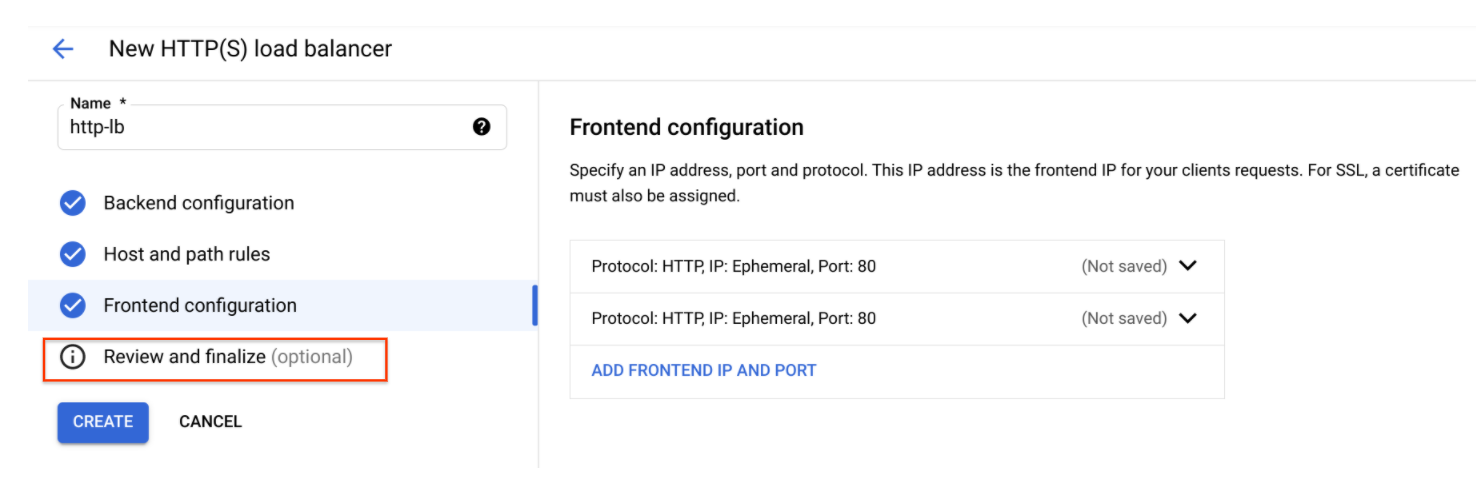
Configure the frontend
The host and path rules determine how your traffic will be directed. For example, you could direct video traffic to one backend and static traffic to another backend. However, you are not configuring the Host and path rules in this lab.
Click on Frontend configuration.
Specify the following, leaving all other values at their defaults:
Property
Value (type value or select option as specified)
Protocol
HTTP
IP version
IPv4
IP address
Ephemeral
Port
80
Click Done.
Click Add Frontend IP and port.
Specify the following, leaving all other values at their defaults:
Property
Value (type value or select option as specified)
Protocol
HTTP
IP version
IPv6
IP address
Auto-allocate
Port
80
Click Done.
Note: HTTP(S) load balancing supports both IPv4 and IPv6 addresses for client traffic. Client IPv6 requests are terminated at the global load balancing layer, then proxied over IPv4 to your backends.
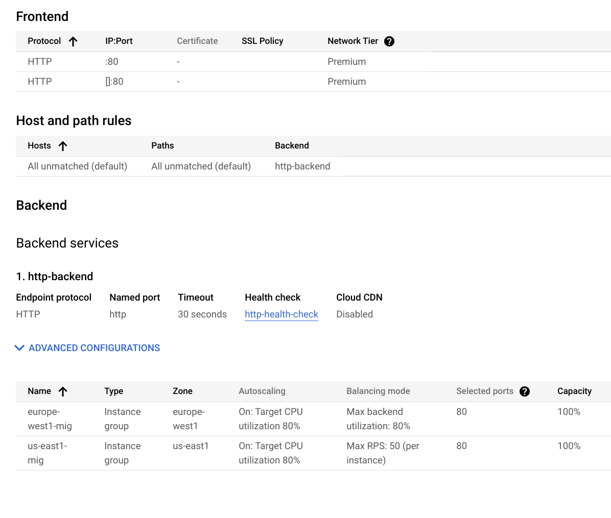
Review and create the HTTP Load Balancer
Click Review and finalize.
Review the Backend services and Frontend.
Click Create.
Wait for the load balancer to be created.
Click on the name of the load balancer (http-lb).
Note the IPv4 and IPv6 addresses of the load balancer for the next task. They will be referred to as
[LB_IP_v4]and[LB_IP_v6], respectively.
Note: The IPv6 address is the one in hexadecimal format.
Click Check my progress to verify the objective.
Configure the HTTP Load Balancer
Check my progress
Task 4. Test the HTTP Load Balancer
Now that you created the HTTP Load Balancer for your backends, verify that traffic is forwarded to the backend service.
The HTTP load balancer should forward traffic to the region that is closest to you.TrueFalse
Access the HTTP Load Balancer
- To test IPv4 access to the HTTP Load Balancer, open a new tab in your browser and navigate to
http://[LB_IP_v4]. Make sure to replace[LB_IP_v4]with the IPv4 address of the load balancer.
Note: It might take up to 5 minutes to access the HTTP Load Balancer. In the meantime, you might get a 404 or 502 error. Keep trying until you see the page of one of the backends.
Note: Depending on your proximity to us-central1 and europe-west4, your traffic is either forwarded to a us-central1-mig or europe-west4-mig instance.
If you have a local IPv6 address, try the IPv6 address of the HTTP Load Balancer by navigating to http://[LB_IP_v6]. Make sure to replace [LB_IP_v6] with the IPv6 address of the load balancer.
Stress test the HTTP Load Balancer
Create a new VM to simulate a load on the HTTP Load Balancer using siege. Then, determine if traffic is balanced across both backends when the load is high.
In the Console, navigate to Navigation menu () > Compute Engine > VM instances.
Click Create instance.
Set the following values, leave all other values at their defaults:
Property
Value (type value or select option as specified)
Name
siege-vm
Region
us-east1Zone
us-east1-cSeries
E2
Note: Given that us-east1 is closer to us-central1 than to europe-west4, traffic should be forwarded only to us-central1-mig (unless the load is too high).
Click Create.
Wait for the siege-vm instance to be created.
For siege-vm, click SSH to launch a terminal and connect.
Run the following command, to install siege:
sudo apt-get -y install siege
Click Check my progress to verify the objective.
Test the HTTP Load Balancer
Check my progress
- To store the IPv4 address of the HTTP Load Balancer in an environment variable, run the following command, replacing
[LB_IP_v4]with the IPv4 address:
export LB_IP=[LB_IP_v4]
- To simulate a load, run the following command:
siege -c 250 http://$LB_IP
The output should look like this:
New configuration template added to /home/cloudcurriculumdeveloper/.siege
Run siege -C to view the current settings in that file
In the Cloud Console, on the Navigation menu (
), click Network Services > Load balancing.
Click Backends.
Click http-backend.
Navigate to
http-lb.Click on the Monitoring tab.
Monitor the Frontend Location (Total inbound traffic) between North America and the two backends for 2 to 3 minutes.
At first, traffic should just be directed to us-central1-mig but as the RPS increases, traffic is also directed to europe-west4-mig.
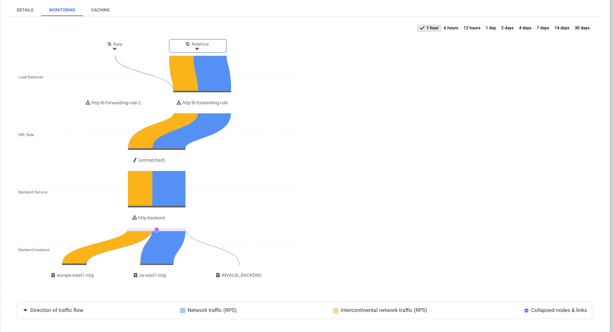
This demonstrates that by default traffic is forwarded to the closest backend but if the load is very high, traffic can be distributed across the backends.
Return to the SSH terminal of siege-vm.
Press CTRL+C to stop the siege.
Task 5. Create Cloud Armor rate limiting policy
In this section you will use Cloud Armor to denylist the siege-vm from accessing the HTTP Load Balancer by setting a rate limiting policy.
- In Cloud Shell, create security policy via gcloud:
gcloud compute security-policies create rate-limit-siege \
    --description "policy for rate limiting"
- Next, add a rate limiting rule:
gcloud beta compute security-policies rules create 100 \
    --security-policy=rate-limit-siege     \
    --expression="true" \
    --action=rate-based-ban                   \
    --rate-limit-threshold-count=50           \
    --rate-limit-threshold-interval-sec=120   \
    --ban-duration-sec=300           \
    --conform-action=allow           \
    --exceed-action=deny-404         \
    --enforce-on-key=IP
- Attach the security policy to the backend service http-backend:
gcloud compute backend-services update http-backend \
    --security-policy rate-limit-siege --global
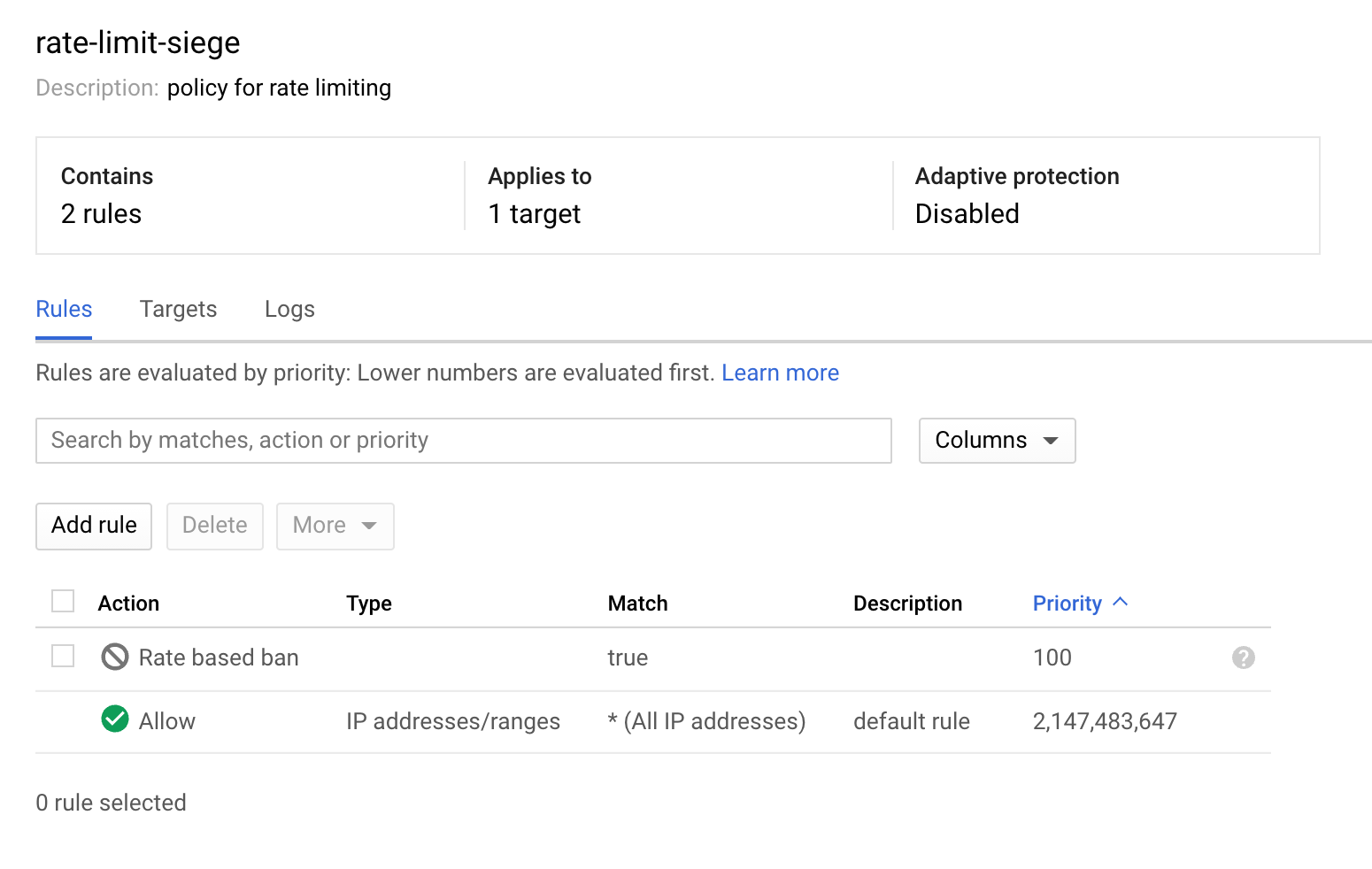
In the Console, navigate to Navigation menu > Network Security > Cloud Armor.
Click
rate-limit-siege. Your policy should resemble the following:
Click Check my progress to verify the objective.
Create Cloud Armor Rate Limiting Policy
Check my progress
Task 6. Verify the security policy
Return to the SSH terminal of siege-vm.
Run a curl against the LB IP to verify you can still connect to it, should receive a 200 response:
curl http://$LB_IP
- In the SSH terminal of siege-vm, to simulate a load, run the following command:
siege -c 250 http://$LB_IP
The command will not generate any output.
Explore the security policy logs to determine if this traffic is also blocked.
In the Console, navigate to Navigation menu > Network Security > Cloud Armor policies.
Click rate-limit-siege.
Click Logs.
Click View policy logs.
On the Logging page, make sure to clear all the text in the Query preview.
Select resource to Application Load Balancer > http-lb-forwarding-rule > http-lb then click Apply.
Now click Run Query.
Expand a log entry in Query results.
Expand httpRequest.
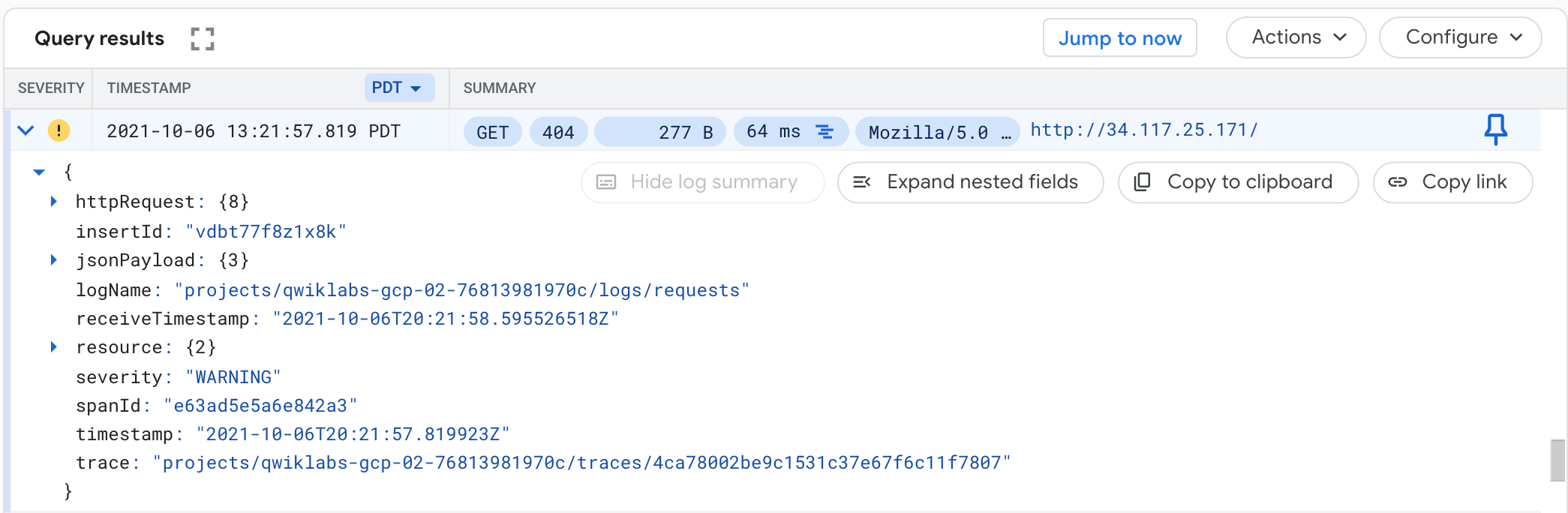
The request should be from the siege-vm IP address. If not, expand another log entry.
Expand
jsonPayload.Expand
enforcedSecurityPolicy.
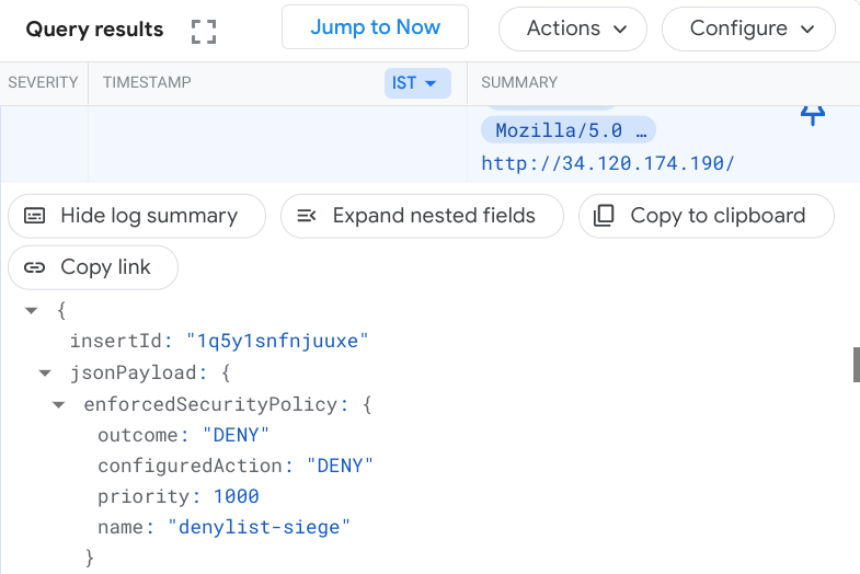
Notice that the configuredAction is to DENY with the name rate-limit-siege.
Note: Cloud Armor security policies create logs that can be explored to determine when traffic is denied and when it is allowed, along with the source of the traffic.
Solution of Lab
curl -LO raw.githubusercontent.com/ePlus-DEV/storage/refs/heads/main/labs/GSP975/lab.sh
source lab.sh
Script Alternative
curl -LO raw.githubusercontent.com/gcpsolution99/GCP-solution/refs/heads/main/GSP/GSP975.sh
sudo chmod +x GSP975.sh
./GSP975.sh